Simon Fell > Its just code > sim racing
Thursday, February 17, 2022
This is part 1 in a series of posts about writing an app that does fuel calculator/strategy for iRacing.
Fuel Calculator
What’s a fuel calculator anyway? Imagine a 30 lap race in a car that can only run 20 laps on a full tank of gas. At some point in the race you need to stop and get more gas. You could stop at lap 10, top up and run to the end, or stop at lap 20 and take half a tank to get you to the end. That one is easy enough to do in your head, but throw in caution laps, fuel saving from drafting, and timed races and it gets harder to keep track of. A Fuel calculator app tracks the status of the car & race from iRacing and reports information the driver can use to help determine strategy, when to stop, when to fuel save.
There are of course a number of existing apps for this with varying degress of sophisitaction but I wanted something to help specifically around multi stop races and fuel saving. In this recent TNT race at Pheonix it would of been useful to know exactly how much fuel was needed to be saved to be able to skip the last pitstop that was only a couple of laps from the end of the race. It’d also be useful to know if you’re hitting that fuel save target or if you can’t, and should stop trying. The worst outcome is you try to fuel save, costing you time and potentially positions, but don’t save enough and have to stop anyway. Which is what happened to me, and quite a few other folks as well.
Why Rust?
iRacing provides a c++ based SDK for accessing telemetry data, and some people have built .NET versions as well. I could of written it in C#, but i find the VS2019 winforms tooling super annoying to use. I was going to use go, but then remembered that Windows Defender seems to consider anything built with go as having a virus in it. This is apparently beyond the ability of Microsoft and Google to fix. But I’ve been learning rust over the last year or so, so thought it’d be an interesting exercise to write it in Rust. The iRacing SDK is based around memory mapped data and a bunch of c structs that include a description of the data as well as the actual telemetry data. Given that there’s going to be a lot of unsafe Rust code to deal with that it’ll be interesting to see how much Rust helps vs gets in the way.
Parts
I broke the problem up into 3 main areas
- Getting data out of and into iRacing.
- Collecting the relevant data from iRacing to construct the current state of the race, as well as calculating additional needed stats like average fuel usage per lap.
- Calculating strategy options given the current state of the race.
We’ll start by looking at the strategy options, and cover the other areas in later posts.
Fuel Strategy
We need various peices of information to be able to generate a guestimate of the later laps. If you want to see the whole code for this part, see strat.rs
- The fuel used and time taken for a typical lap.
- The fuel used and time taken for a lap under yellow flag conditions.
- How much fuel is currently in the car.
- What’s the maximum amount of fuel the car can hold.
- How the race ends. (laps, time, both)
- If we’re currently under yellow, and if so, how many more yellow laps are expected.
A struct to hold this is easy enough, getting some of this data not so much. To know when you can pit, you need to know when the race will end. Races can be setup in different ways, a fixed number of laps, a fixed amount of time, or a combo laps & time, where the race ends when the first of either is reached. My first instinct was to capute this with a pair of Option fields, e.g.
pub struct EndsWith {
    laps: Option<usize>,
    time: Option<Duration>,
}
The one downside to this is that this struct can be constructed in an invalid state, e.g. EndsWith{None,None}. Ideally
we’d use the type system to not let this happen at all, compile time checks are better than runtime checks. We can use
enum’s for this, enums in Rust are much more powerful than in other c’ish languages. In my Rust journey so far, I find
that enums are often the answer.
pub enum EndsWith {
    Laps(usize),
    Time(Duration),
    LapsOrTime(usize, Duration),
}
Now you can’t construct an EndsWith that doesn’t specify one of the valid options.
So here’s the struct that defines a strategy calculation request.
pub struct Rate {
    pub fuel: f32,
    pub time: Duration,
}
pub struct StratRequest {
    pub fuel_left: f32,
    pub tank_size: f32,
    pub yellow_togo: usize,
    pub ends: EndsWith,
    pub green: Rate,
    pub yellow: Rate,
}
First up we need to work out how many laps we can do with the current fuel, then fill up and repeat until the end of the race. We also need to deal with being under yellow flag conditions, where much less fuel is used, and the laps take much longer. So the first few laps we apply might be yellow flag laps before the race goes back to racing. Or there’s the edge case where the race will finish under the yellow flag. I had a few goes at this, the simple case where there’s no yellows and a known number of laps is pretty simple (divide fuel by rate to get number of laps). But then dealing with timed races is a challenge, you’d have to calculate the expected number of laps first. And then dealing with yellows makes it even messier. I finally settled on an approach that just walks forward one lap at a time applying the relevant rate. This can also accumulate time to determine when the end is.
I built an Iterator chain that provides the stream of future laps, this can then be iterated over and broken up into stints. I like how the code ended up, it seems much tidier to me than the previous attempts that had various loops and a bunch of variables tracking different states.
let yellow = iter::repeat(self.yellow).take(self.yellow_togo);
let mut tm = Duration::ZERO;
let mut laps = 0;
let laps = yellow.chain(iter::repeat(self.green)).take_while(|lap| {
    tm = tm.add(lap.time);
    laps += 1;
    match self.ends {
        EndsWith::Laps(l) => laps <= l,
        EndsWith::Time(d) => tm <= d,
        EndsWith::LapsOrTime(l, d) => laps <= l && tm <= d,
    }
});
Now we can iterate over laps accumulating time & fuel and determine where each run between pitstops occurs (called stints)
let mut stints = Vec::with_capacity(4);
let mut f = self.fuel_left;
let mut stint = Stint::new();
for lap in laps {
    if f < lap.fuel {
        stints.push(stint);
        stint = Stint::new();
        f = self.tank_size;
    }
    stint.add(&lap);
    f -= lap.fuel;
}
if stint.laps > 0 {
    stints.push(stint);
}
There’s probably a way to write that as part of the iterator chain. I find that thinking about it in this 2 peices easier to think about though.
From here its straight forward enough to create a Pitstop at the end of each stint (except the last one). If the last stint doesn’t require a full fuel load, then the “spare” capacity can be used to pull a pitstop forward. This creates the Pitstop windows, the earlest and latest that you can make the pitstop. For the 30 lap race, 20 lap tank example at the start, this would generate a Pitstop window that begins at lap 10 and ends at lap 20.
Now we have enough information to answer the fuel save question. If I can run laps that use less fuel, can I get rid of a pitstop? If you want to skip the last pitstop, then you’d need to have saved enough fuel to complete the last stint. We know what that is from when we built the Stints. We can include that in our results. Later on we’ll take that info to compute a fuel usage target we can display.
As all the input needed to generate this strategy result is managed externally, it easy to write unit tests for this.
#[test]
fn strat_two_stops() {
    let d = Duration::new(40, 0);
    let r = StratRequest {
        fuel_left: 9.3,
        tank_size: 10.0,
        max_fuel_save: 0.0,
        yellow_togo: 0,
        ends: EndsWith::Laps(49),
        green: Rate { fuel: 0.5, time: d },
        yellow: Rate { fuel: 0.1, time: d },
    };
    let s = r.compute();
    assert_eq!(vec![18, 20, 11], s.laps());
    assert_eq!(vec![Pitstop::new(9, 18), Pitstop::new(29, 38)], s.stops);
}
Next time we’ll cover the calculator, this tracks the state of the race, the fuel usage on prior laps to feed into the strategy builder.
Monday, July 5, 2021
The last post ended with me fighting with prints curling and eventually coming off the bed. I decided to grab a single layer test print and see what the first layer was doing.
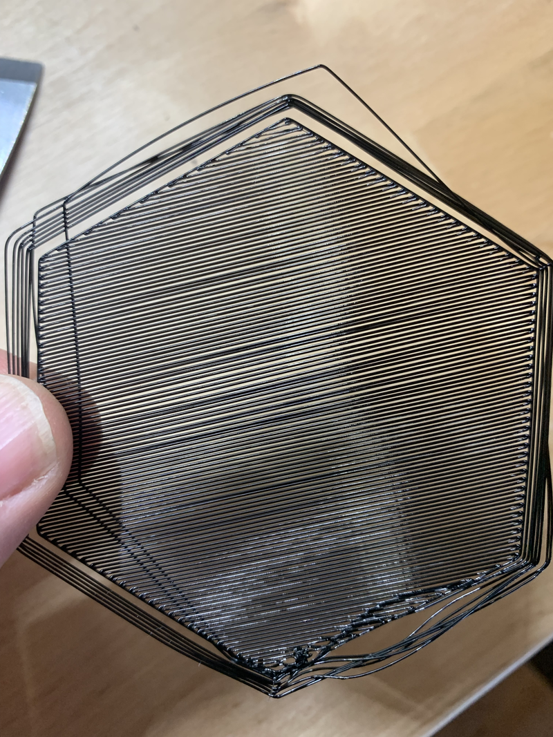
Wow that's a terrible first layer, no wonder I've been having issues. It looks like its not close enough to the bed. I'd recently installed a BLTouch, so next step is to do a print without the bed leveling mesh enabled.
That one turned out better, the lines are stuck to each other and the bed. Part of the BLTouch install involves determining the distance between the nozzle and the activation point of the probe. Something must be off there. I carefully go through the process to determine the probe and nozzle offset and then have it measure the bed levelling mesh again. Now a print with the mesh applied.
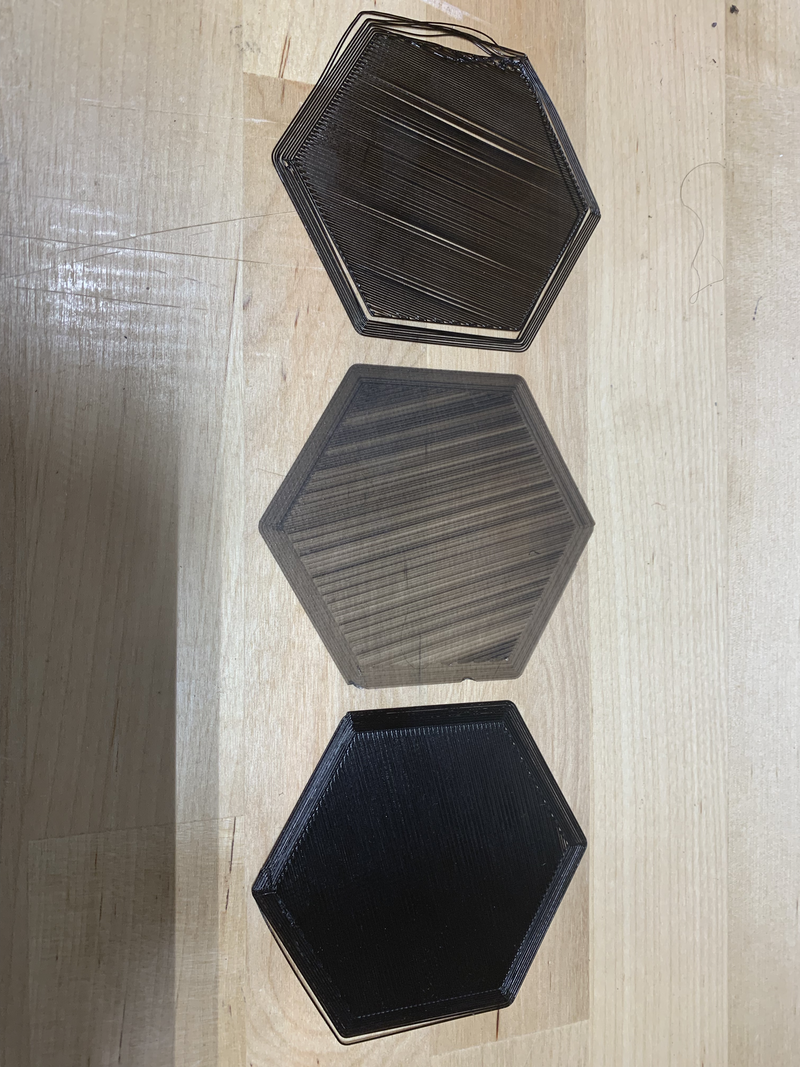
That one turned out much better, even thickness, good bed adhesion. Time to kick off the 15 hour bearing mount print. Success, it stays stuck to the bed, time to assemble that last actuator.
3 first layer prints. From top to bottom, initial print, no auto bed levelling,
auto bed levelling with recalibrated probe to nozzle setting.
Wednesday, June 9, 2021
I've been working on an SFX100 build. Yeah i know its been a long time, you thought it was long finished. Not so much.
Back in October I'd started on the 3D printing. I got a single set of prints completed, and went through the process to assemble the first actuator. This went reasonably well. The instructions are pretty good, I used a dab of superglue to hold the o-ring onto the bump stop and discovered that you can't get the grease gun on once the slider is fitted to the ball screw. Easy enough to unscrew the slider and then grease the ball-screw. With this success I was in full on 3D printing mode for a couple of weeks to print parts for the remaining 3 actuators. A couple of weeks later, and I'm assembly the 3 remaining actuators. That's when I started running into problems.
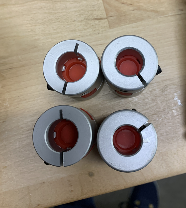
First off, I noticed that the couplers were different sizes, I'd gotten 2 the right size, and 2 that were smaller.
 .
.
The folks over at ntl-bearing.com quickly sent me 2 replacements.
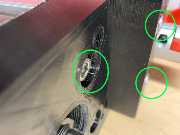
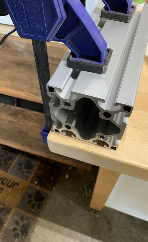
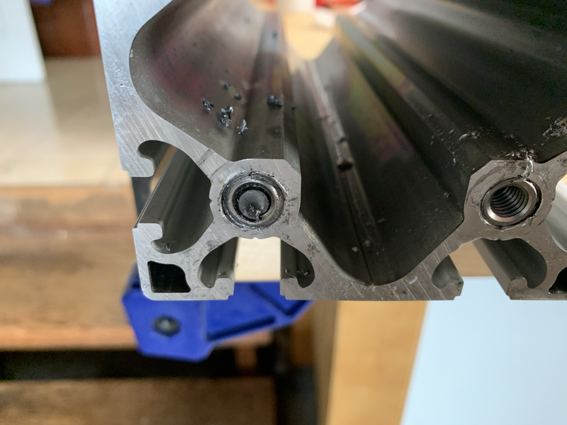
Then i hit bigger problems. Remember back when I said it was important to get the profile inserts in square, this is why.
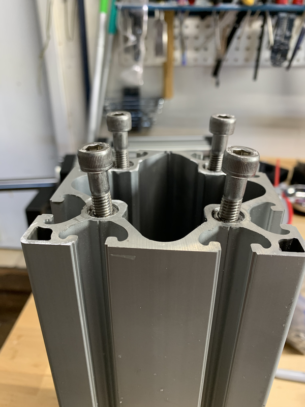
You can see here that the left side bolts aren't square to the profile, especially
the front left. The top bearing mount design has standard clearance holes for the bolt, but is deep enough that with the
angled bolt you can't get all the bolts through the bearing mount and into the profile. One profile I couldn't get the
bearing mount on at all. The second one I managed to get on, but it got pulled off center and the actuator travel was
really stiff and noisy. You can't get the inserts out of the profile, so its either buy new profile and redo these 2, or
redesign the bearing mount to allow the bolts a bit more room. This only reenforces my earlier recommendation to build the
Item24 variation and have Item24 tap the profile for you.
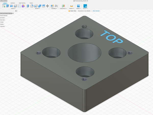
I set about tweaking the bearing mount design. Fusion360 wouldn't import the STL file due to the large number of triangles
in it as a result of their being threaded holes in the model. And only STL files are published for the 3d printed parts.
So i set about recreating it from scratch in Fusion 360. This wasn't too bad, its a rectangle with some holes in it. Most
of the time was spent on checking the dimensions of the hole for the bearing to sit in. I then updated the model to add
a small slot to the bolt holes.
I printed a draft and test fit it and everything seemed okay. Went back and did final prints of 2 more. A few days
later back to assembly. Now, when i did the test fit, i was concentrating on the bearing placement, getting the bolts in
and tightened up and checking that the screw-ball was still square and travelled okay. What I didn't check was the motor
mount that fits on top of the bearing mount. You can see here that I screwed up the depth of the bolt recess and the top
of the bolts protrude slightly above the top of the bearing mount. (left good, right bad)
 .
.
Bah. back to Fusion 360, tweak the design, print some more.
We're now well into December, and it is much colder (relatively, it is California after all) in the garage where the 3D printer lives than it was before. I tried printing the 2 bearing mounts again, and had all sorts of issues. First layer wouldn't stick, and very poor adhesion between layers. After a number of attempts and some research I found some discussions of how the ambient temperature can affect prints. I experimented with different hot-end temperatures and was able to get some better prints, I ended up printing at 220 vs the original temperature of 200. At this point I was tired of fighting the printer on 15 hour prints, and turned to a couple of other projects for a while.
After having enough successful smaller prints, I finally got around to trying to print the bearing mounts again. I kicked off the
print, it seemed to be going well. Checked in after 13 hours, still going strong. Come back when it should of finished to find
this. 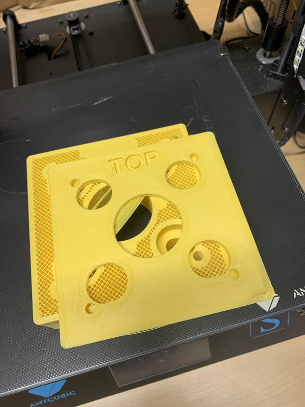
I was (and still am) baffled by this, it looks like it just shifted the X and Y
by 100mm at a particular layer. This doesn't seem to be the regular layer shift problems, which are typically mechanical and accumulate
small amounts of drift over many layers. The fact that both X and Y are offset the same amount also implies its not a mechanical issue.
Possibly a bug in the slicer? Possibly something caused Octoprint to miss some steps from the g-code? I still don't know. Without
knowing why it failed I was loathed to try it again. I put it down again, and went and worked on some other projects.
More time passes, I don't see the issue again. I have a 12 hour print go fine. I finally get around to trying the bearing mount again.
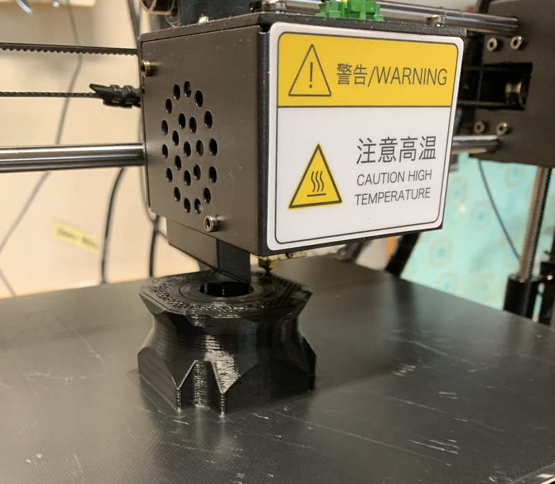
That one comes out fine, some slight curling at the corners, but that's to be expected and not a problem. I assemble and test actuator #3,
success!. I kick off the final print, and a few hours later am greeted by this.
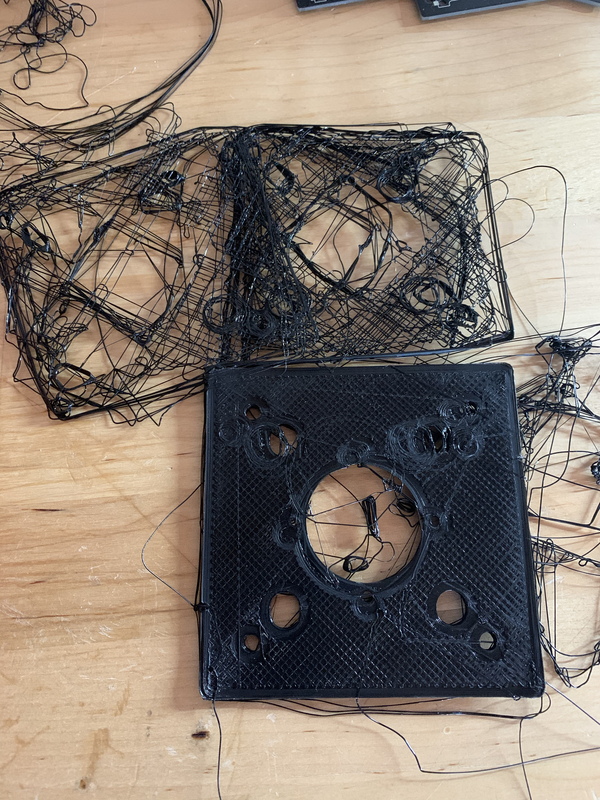 .
.
As far
as i can tell, the corners curled enough to unstick the print from the bed, and chaos ensued. More research, I find some recommendations
to start with the part cooling fan off and have it ramp up over the initial layers. I fiddle with slicer settings some more, and kick
off another print. Its running as a type this. It looks okay so far, there's some curling but its less than it used to be. Hopefully
this one completes successfully.
Update: It didn't
Wednesday, October 21, 2020
Previously I'd extracted the sheared bolt from the 2nd piece of profile. 2 more to go. At this point, I've gotten to an approach that works reasonably well, counter sink the hole, use the M12 tap to tap the hole, then install the insert. The larger tap wrench and long handled wrench make this easier, but its still a workout. The main thing to watch is that the tap is kept square to the profile, and the insert is kept square while installing. I got the final 16 inserts installed into the last 2 pieces of profile and step 1 is done!.
There's a variation of the build that uses profile from Item24 rather than Kinetic. Having dealt with the thread inserts which was a giant PIA, I'd highly recommend the Item24 variation instead. The Item24 version uses an M10 thread in the profile and M10 bolts to secure the bearing mounts, no thread inserts involved. Also, Item24 can supply the profile with the threads already cut, vastly simplifying what is the most annoying step of the build.
Tuesday, October 20, 2020
The 3D printer is still whirring along, few days left there. The motors and drives turned up, so I did a sanity test on all them to make sure there's no issues. This was straightforward enough, wiring the motor to the driver, plug the encoder cable in, and wire power to the driver. Use the jog function to check that the motor spins. The opensfx docs cover this well.
Mains voltage can kill you! make sure you know what you're doing, or get help from a qualified electrician.
Saturday, October 10, 2020
After i ordered the parts, I got started on the 3D printing, there's a lot of it. There's 5 parts to be printed for each actuator. One set of parts takes about 50 hours to print. You can get these printed via a print service. But now that printers are less than $300 it's more economical to buy a printer and print them yourself. Plus as a bonus you'll have a 3D printer at the end of it.
I went with the Anycubic i3 Mega S. It's easy to assemble, just 4 bolts and you're up and running. Getting the print bed level is a PIA, but that seems to be true for all the 3D printers. The Prusa i3 and Ender printers are also popular.
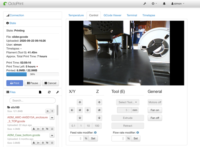
One of the first things i printed was a raspberry pi case/mount so that I could setup Octoprint. This lets you control and monitor your printer from a browser, great for keeping an eye on those 12 hour prints without going out to the garage every time. I use a Sony PS Eye webcam with mine that i picked up for $15. No need to spend more than that for the webcam.
Dimensional accuracy of the prints is important, especially for the slider. Its worth spending the time on some calibration prints first. You'll also want to play close attention to the print profile in the slicer software. The prints are not strong enough with the typical default profile. I setup a custom profile that follows the recommendations. If you're confident in the calibration then go ahead and print all 4 sets. I printed one set first and test fit it to the profile before starting to print the rest.
Tuesday, October 6, 2020
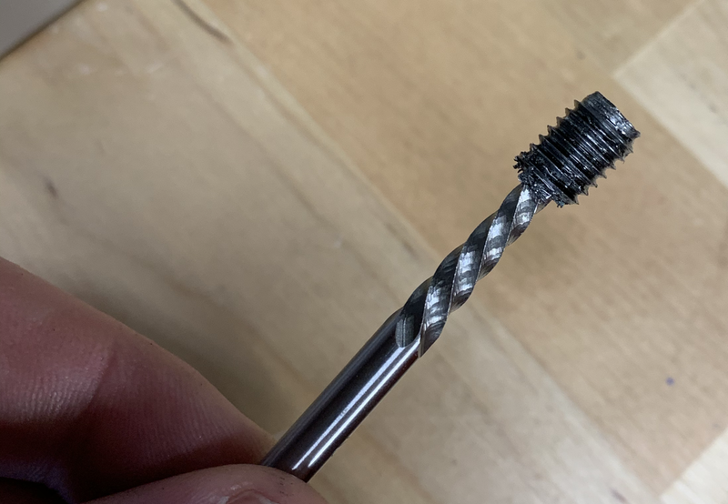
If you recall from the previous post I had a sheared bolt inside the thread insert. The bolt extractor tool turned up, so lets fix that!
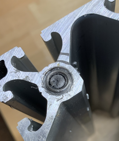
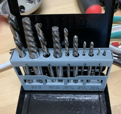
Drill a hole in the center of the bolt, then tap the extractor into the hole.
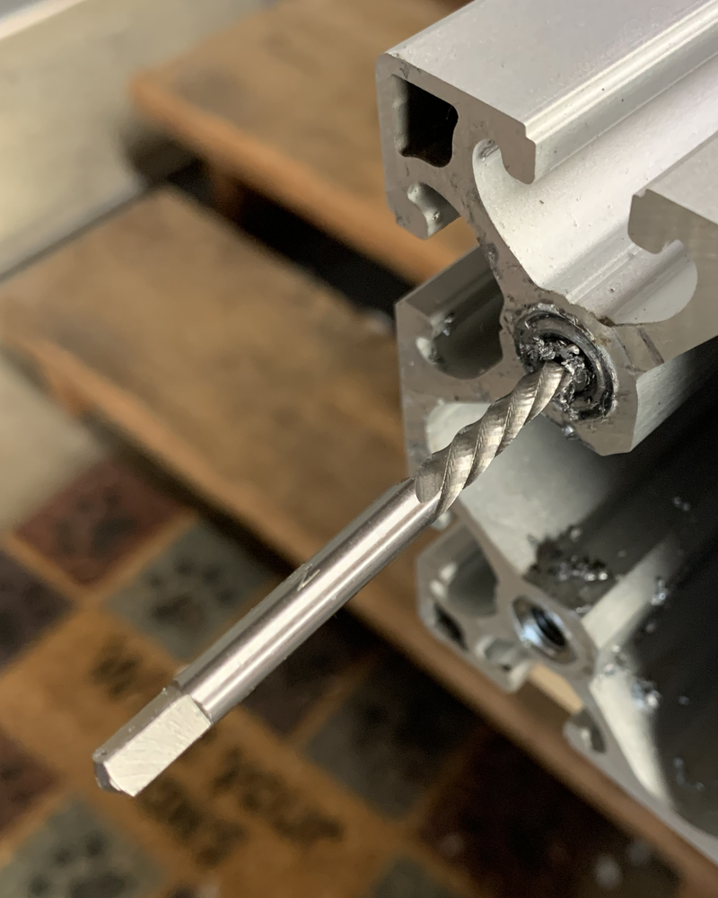
Now turn the extractor anti-clockwise using a tap handle, and its out!
Crisis averted!, onward. On the remaining profiles I'm going to counter sink the hole a little before installing the thread inserts, this should make getting them flush easier.
Saturday, October 3, 2020
First step in the actuator build is to install the threaded inserts into the aluminum profile. 4 Profiles, 4 inserts per end, 32 total.
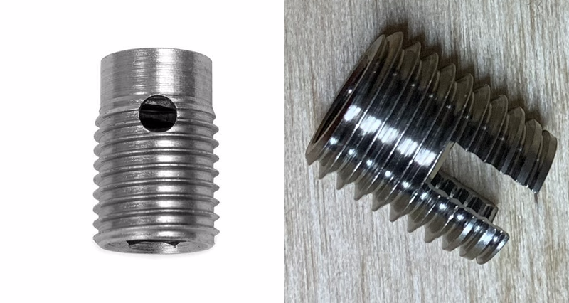
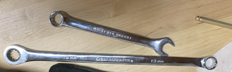
As mentioned in the ordering post, I brought my aluminum profile from a fellow iRacer. They didn't however have the matching thread inserts that kinetic sells. I wasn't able to find these from anywhere, and ended up with some different ones, just to keep things interesting.
Kinetic insert left, inserts I ended up with on the right. Note that the Kinetic insert has a nice shoulder that helps keep things square when inserting them. Another nice thing about the Kinetic insert is that it has an internal hex, allowing it to be installed with an allen wrench. The info for my inserts mention a specific insertion tool, but i couldn't find anywhere selling them. The insertion tool though is basically a threaded shaft with a nut on it, I made my own with an M8 bolt and nut.
The inserts claim to be self tapping, but have no leading taper, making them very hard to get started. I ended up using a M12 tap in the profile to cut a starting thread that the insert can then use.
2 down, 30 to go, ughh, these are a lot of work. First tapping the aluminum, then the installing the insert. I tried using my battery impact driver, but it didn't have the torque needed to install the insert. One internet order later, i tried a larger AC powered impact driver. That had way to much torque, it mostly ended up stripping the threads on the bolt rather than inserting the insert.
One more internet order later i had a much longer wrench, and one with a built in ratchet end. This made installing the inserts by hand much less work. But that longer leverage means more torque, combine that with the damage done earlier with the impact driver and bingo, one snapped bolt, arrrrgggggghhh.
At this point I've spent a week on this and gotten a grand total of 7 installed inserts. One with a broken bolt stuck in it. One more internet order. when the bolt extract tool turns up this adventure will continue.
Thursday, October 1, 2020
The SFX-100 is an open source/DIY motion actuator for use with racing or flight simulators. I've been enjoying iRacing this year, and thought this would a fun project to work on.
Step 0 is to order everything, there's parts needed from a number of different suppliers, and some of these take weeks or even a month or two to be delivered. The original project parts list is heavy on european suppliers, reflecting where all the development was done. This post on Race Department details better options for US based folks.
I had no issues ordering from ntl bearing or Master Jiangs store on aliexpress, those parts turned up in a couple of weeks. ntl-bearings also now can supply the servo & drives, if you want to cut down the number of different places to order from.
The big lead time is the aluminum profiles from Kinetic, they're a B2B supplier and not set up for lots of little consumer orders. Reports are that it can take 1-2 months for those orders to turn up in the US. I lucked out, someone on the iRacing forums was selling a set of the profiles after decided not to do the build. I purchased those and had them in a week.
These are the main parts, the rest is a laundry list of bits and pieces, all easily available.
While waiting for everything to turn up, its a good time to get started on the 3D printing, there's a lot of it needed.